- 您现在的位置:买卖IC网 > Sheet目录529 > UPC2709TB-EVAL (CEL)EVAL BOARD FOR UPC2709TB
�� �
�
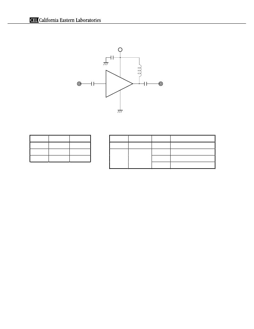
�PC2709TB�
�TEST� CIRCUIT�
�V� CC�
�1� 000� pF�
�C� 3�
�6�
�L�
�IN�
�50�
�C� 1�
�1�
�4�
�C� 2�
�50�
�OUT�
�1� 0� 0� 0� p� F�
�COMPONENTS� OF� TEST� CIRCUIT� FOR�
�2,� 3,� 5�
�1� 0� 0� 0� p� F�
�MEASURING� ELECTRICAL� CHARACTERISTICS�
�EXAMPLE� OF� ACTURAL� APPLICATION� COMPONENTS�
�T� y� p� e�
�V� a� l� u� e�
�T� y� p� e�
�V� a� l� u� e�
�O� p� e� r� a� t� i� n� g� F� r� e� q� u� e� n� c� y�
�C� 1� to� C� 2�
�C� 3�
�L�
�Bias� Tee�
�C� a� p� a� c� i� t� o� r�
�B� i� a� s� T� e� e�
�1� 000� pF�
�1� 0� 0� 0� p� F�
�1� 0� 0� 0� n� H�
�C� 1� to� C� 3�
�L�
�Chip� capacitor�
�C� h� i� p� i� n� d� u� c� t� o� r�
�1� 000� pF�
�3� 0� 0� n� H�
�1� 0� 0� n� H�
�100� MHz� or� higher�
�1� 0� M� H� z� o� r� h� i� g� h� e� r�
�1� 0� 0� M� H� z� o� r� h� i� g� h� e� r�
�10� nH�
�1.0� GHz� or� higher�
�INDUCTOR� FOR� THE� OUTPUT� PIN�
�The� internal� output� transistor� of� this� IC� consumes� 20� mA,� to� output� medium� power.� To� supply� current� for� output�
�transistor,� connect� an� inductor� between� the� V� CC� pin� (pin� 6)� and� output� pin� (pin� 4).� Select� large� value� inductance,� as�
�listed� above.�
�The� inductor� has� both� DC� and� AC� effects.� In� terms� of� DC,� the� inductor� biases� the� output� transistor� with� minimum�
�voltage� drop� to� output� enable� high� level.� In� terms� of� AC,� the� inductor� make� output-port� impedance� higher� to� get�
�enough� gain.� In� this� case,� large� inductance� and� Q� is� suitable.�
�CAPACITORS� FOR� THE� V� CC� ,� INPUT,� AND� OUTPUT� PINS�
�Capacitors� of� 1� 000� pF� are� recommendable� as� the� bypass� capacitor� for� the� V� CC� pin� and� the� coupling� capacitors�
�for� the� input� and� output� pins.�
�The� bypass� capacitor� connected� to� the� V� CC� pin� is� used� to� minimize� ground� impedance� of� V� CC� pin.� So,� stable� bias�
�can� be� supplied� against� V� CC� fluctuation.�
�The� coupling� capacitors,� connected� to� the� input� and� output� pins,� are� used� to� cut� the� DC� and� minimize� RF� serial�
�impedance.� Their� capacitance� are� therefore� selected� as� lower� impedance� against� a� 50�
�load.� The� capacitors� thus�
�perform� as� high� pass� filters,� suppressing� low� frequencies� to� DC.�
�To� obtain� a� flat� gain� from� 100� MHz� upwards,� 1� 000� pF� capacitors� are� used� in� the� test� circuit.� In� the� case� of� under�
�10� MHz� operation,� increase� the� value� of� coupling� capacitor� such� as� 10� 000� pF.� Because� the� coupling� capacitors� are�
�determined� by� equation,� C� =� 1/(2� Rfc).�
�6�
�Data� Sheet� P12653EJ3V0DS00�
�发布紧急采购,3分钟左右您将得到回复。
相关PDF资料
UPC2710TB-EVAL-A
EVAL BOARD FOR UPC2710TB
UPC2711TB-EVAL
EVAL BOARD FOR UPC2711TB
UPC2726T-E3
IC 1.6GHZ DIFFEREN MMIC AMP TO6
UPC2745TB-EVAL-A
EVAL BOARD FOR UPC2745TB
UPC2747TB-E3-A
MMIC AMP 900MHZ SOT-363
UPC2749TB-EVAL
EVAL BOARD FOR UPC2749TB
UPC2756TB-E3-A
MMIC DOWN CONV 3V 2GHZ SOT363
UPC2758TB-E3-A
MMIC DOWN CONV 3V 2.5GHZ SOT363
相关代理商/技术参数
UPC2709TE3
制造商:未知厂家 制造商全称:未知厂家 功能描述:Analog IC
UPC2709T-E3
制造商: 功能描述: 制造商:NEC Electronics Corporation 功能描述: 制造商:undefined 功能描述:
UPC2709T-E3-A
功能描述:MMIC AMP 2.5GHZ SOT-26 RoHS:是 类别:RF/IF 和 RFID >> RF 放大器 系列:- 标准包装:3,000 系列:- 频率:100MHz ~ 6GHz P1dB:9.14dBm(8.2mW) 增益:15.7dB 噪音数据:1.3dB RF 型:CDMA,TDMA,PCS 电源电压:2.7 V ~ 5 V 电流 - 电源:60mA 测试频率:2GHz 封装/外壳:0505(1412 公制) 包装:带卷 (TR)
UPC2709TE3CUT
制造商:CLB 功能描述:
UPC271
制造商:NEC 制造商全称:NEC 功能描述:Precision Voltage Comparators
UPC2710
制造商:未知厂家 制造商全称:未知厂家 功能描述:Analog IC
UPC2710T
制造商:NEC 制造商全称:NEC 功能描述:1.5 GHz SILICON MMIC WIDE-BAND AMPLIFIER
UPC2710TB
功能描述:射频放大器 5V Med Power Pwr Amp RoHS:否 制造商:Skyworks Solutions, Inc. 类型:Low Noise Amplifier 工作频率:2.3 GHz to 2.8 GHz P1dB:18.5 dBm 输出截获点:37.5 dBm 功率增益类型:32 dB 噪声系数:0.85 dB 工作电源电压:5 V 电源电流:125 mA 测试频率:2.6 GHz 最大工作温度:+ 85 C 安装风格:SMD/SMT 封装 / 箱体:QFN-16 封装:Reel